RX1 Humanoid Arm Assembly Instruction
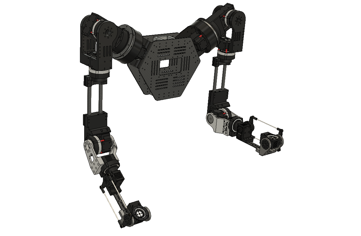
This article is about the assembly of the arm for the RX1 humanoid robot.
- Section 1 covers the background servo information
- Section 2 lists out all the components to be prepared
- Section 3 includes all the assembly steps
Section 1 Background
RX1 is an opensource humanoid with two human-scale arms (no legs). It's built with low-cost servo motors (see more information in the previous post rx1 servo).
For the whole robot, here are the number of servos you need. Depending on whether you want to build two arms or one arm, hand or gripper, whether to build head and torso, you can make adjustment accordingly.
- For 2 arms:
- 14 x Feetech STS3215 servo (30kg.cm version)
- Extra note: so each arm has 7 servos, 4 of which needs 3d printed gearboxes
- 14 x Feetech STS3215 servo (30kg.cm version)
- For 2 hands (each hands has five fingers and 1 thumb rotational joint):
- 8 x Feetech SCS0009 servo (Single shaft)
- 4 x Feetech STS3032 servo (Single shaft)
- For 2 grippers
- 2 x Feetech STS3215 servo (20kg.cm version)
- Extra note: 30kg.cm is also fine
- 2 x Feetech STS3215 servo (20kg.cm version)
- For 1 head
- 3 x Feetech STS3215 servo (20kg.cm version)
- Extra note: 30kg.cm is also fine
- 2 x Feetech SCS0009 servo (Single shaft)
- 3 x Feetech STS3215 servo (20kg.cm version)
- For 1 torso
- 3 x Feetech STS3215 servo (30kg.cm version)
- Extra note: all 3 of them need 3d printed gearboxes
- 3 x Feetech STS3215 servo (30kg.cm version)
Section 2 Preparation
You can obtain the CAD file and all 3D printed parts through the rx1_arm_hardware github repo.

Here are all the parts needed:
- Shoulder (for one arm):
- 3D printed parts
- 2 x STS3215 servo with 3D printed gearboxes
- 18 x M3 screws (30mm)
- 16 x M3 screws (25mm)
- 38 x M3 screws (20mm)
- 4 x M3 screws (15mm)
- 8 x M3 screws (10mm)
- 1 x M3 screw (8mm)
- 1 x 6708 bearing
- 1 x 6815 bearing
- 2 x 6815 bearing plate
- Note that it can be CNC cut metal sheets, or laser-cut carbon fiber plate. If you want to use 3D printing, you may need to increase the thickness of the top plate to make it stronger.
- Upper arm (for one arm):
- 3D printed parts
- 2 x STS3215 servo with 3D printed gearboxes
- 4 x M3 screws (30mm)
- 4 x M3 screws (25mm)
- 12 x M3 screws (15mm)
- 4 x M3 screws (10mm)
- 8 x M3 nuts
- 1 x 6706 bearing
- 2 x 15cm tube
- They are carbon fiber tubes. Note that it’s dangerous to cut carbon fiber by yourself due to the dust produced during cutting. I recommend getting the carbon fiber tubes cut to the right length by your vendor. Also, you can potentially redesign the upper arm to replace the carbon fiber tube with 3D printed parts.
- Forearm (for one arm):
- 3D printed parts
- 3 x STS3215 servo
- 10 x M3 screws (25mm)
- 4 x M3 screws (20mm)
- 12 x M3 screws (15mm)
- 23 x M3 screws (10mm)
- 20 x M2 self-tapping screws (5mm)
- 1 x 6708 bearing
- 4 x 6706 bearings
- 2 x linkage_14mm
- They can potentially be replaced with a 3D printed part (you need to do the design yourself) with thrust bearings.
- Mounting:
- 3D printed parts
- 2 x hrc5_torso_plate
- They are laser-cut carbon fiber plates. Note that it’s dangerous to cut carbon fiber by yourself due to the dust produced during cutting. I recommend getting the carbon fiber plate cut by your vendor. Also, you can potentially redesign the part to make a thicker (for example 10cm thickness) 3D printed version of it.
- 4 x 70cm 4040 extrusions
- 8 x M5 screws (10mm) & M5 t-slot
- 12 x M3 screws (10mm)
- 4 x 2040 corner bracket sets
Section 3 Assembly
Checkout the video and drawings below for the asembly process. Overall it should take about 1 to 2 hours.
Step 1 Shoulder
Note that you need to disassemble the gearbox for the first shoulder servo before assembling it.


Step 2 Upper arm


Step 3 Forearm


Step 4 Mounting (Optional)
The following pictures demonstrates one potential way to mount the arm. Note that it is not super sturdy and you can decide whether to go with this design or build something more sturdy (which is also something I plan to do later).


What's next:
Will go through all the remaining hardware parts including hand, head, torso etc. and software setup in the following weeks. I am aiming to make one to two posts per week.
If you have any question or feedback (for the design itself or the way it's presented) please leave comments below. Also, please subscribe to see the latest updates!
Member discussion