RX1 Humanoid Servo Assembly Instruction
This article is about the assembly of the servo motor gearboxes for the RX1 humanoid robot.
- Section 1 covers the background of why this solution is chosen
- Section 2 lists out all the components to be prepared
- Section 3 includes all the assembly steps
Section 1 Background
Servo motors are usually the most expensive components in humanoid robots. There are three main types of servo motors as listed below:
- RC servo: You can control the position of the output with pwm signal. For anything more advanced such as speed and acceleration control you would need extra firmware running on your own MCU (for example like this). Another downside is that you don't get any feedback such as position, torque, current etc.
- Serial bus servo: You can control the position, speed, acceleration and set output pwm limit and even current limit sometimes through USB-serial signals. Dynamixel and Feetech are two good examples.
- BLDC servo: You can directly control the torque output and they usually use CAN bus communication and have low-gear ratio. They are the most popular solution for advanced legged robots since they have high torque and at the same time can be compliant through torque control. However they can be complex to work with and require more advanced controller firmware or software that calculates the torque output to work properly.

Since the main part of the RX1 humanoid robot are arms (no legs!) and doesn't require advanced dynamics control for simple pick and place tasks (similar to the Aloha project), thus I decided to go with the serial bus servos.
Compared to Dynamixel, Feetech's price is way lower for servos with similar levels of torque. Feetech servo, in particular STS3215 (30kg.cm version) is chosen.

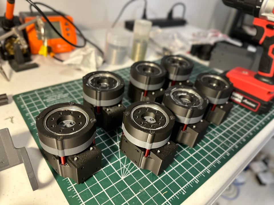
There are 7 joints for each arm and 3 joints for the torso. To increase the torque of the first 4 joints of each arm and the 3 torso joint, a 1:3 gear ratio planetary box is added for each of those servos. And that's what this article is about!

Section 2 Preparation
You can obtain the CAD file and all 3D printed parts through the rx1_servo_hardware github repo.

Here are all the parts needed:
- Satellite gear:
- 4 x Satellite gear (3d printed)
- 1 x Satellite top (3d printed)
- 1 x Satellite base (3d printed)
- 4 x countersunk m3 screw (20mm)
- 1 x 6704 bearing
- 8 x MR63ZZ bearing (notes from 2024-07-10: this was previously mistakenly listed as 608ZZ, which was pointed in the comments below so I updated it to the correct naming MR63ZZ today)
- 4 x spacer (m3x7x1)
- Ring gear:
- 2 x ring gear parts (note that the two bodies in the ring gear needs to printed separately)
- 4 x countersunk m3 screw (30mm)
- 1 x 6708 bearing
- Sun gear and servo:
- 1 x sun gear (3d printed)
- 1 x generic base sts3215 (3d printed)
- 4 x countersunk m3 screw (30mm)
- 4 x m3 screw (8mm)
- 1 x m3 screw (10mm)
- 2 x self tapping m2 screw (8mm)
- 1 x STS3215 30kg.cm (example link)
- 1 x servo horn (comes with the servo)
- 4 x m3x5x15 spacer (example link)
Section 3 Assembly
Checkout the video and drawings below for the asembly process. Overall it should take about 15min to 20min.
Step 1 Satellite gears

Step 2 Ring gear

Step 3 Sun gear and servo

What's next:
Feetech servo comes with Windows debug software as well as C++ and Python SDK. You can either request from your vendor or download directly through their official repo (only in Chinese). I will also make a separate tutorial on wiring and configuration setups.
If you have any question please leave comments below. Also, please subscribe to see the latest updates!
Member discussion